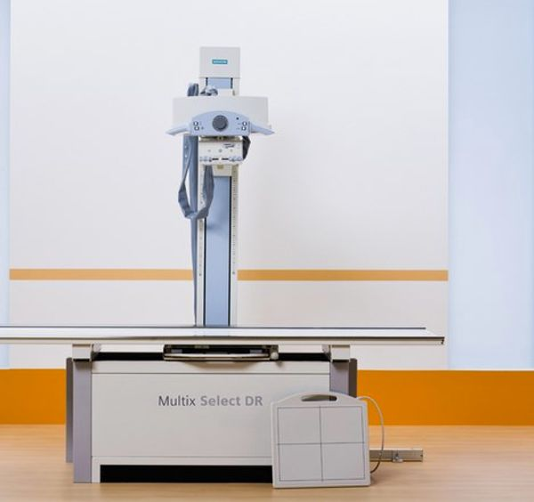
Error 0001 and 0023
RE: DR Systems Report Post

There are two separate 24V power supplies for this system - have you verified the output of them as they are inputs to the D800 board which is what activates the relays you are talking about. These can be checked at X36 & X73 on the D800 board. LED indicators for these are V103 & V104.
If you need additional help, please contact Technical Prospects and we will be happy to assist you.
John DiPasquale
Technical Trainer | Technical Prospects
1000 S. County Road CB, Appleton, WI 54914
www.technicalprospects.com
+1 (920) 757-6583
Report Post
We have check one power supply in the left corner just on the bottom of the board. I do not have a diagramm unfortunalty. This one reads 23 V on 33 an 34 as if I remember right. The other output 31 and 31 ist 220V. I will check the LED tomorrow. Where is the second power supply located?
Many thanks for your help! We are realy in urgent need.
Report Post

The power supplies come off the T3 transformer using cables W417 & W416 as inputs to them. The outputs of the power supplies use cables W343 and W342 and connect to the D800 board at 24V_DI.X7 and 24V_BI.X6 respectively.
John DiPasquale
Technical Trainer | Technical Prospects
1000 S. County Road CB, Appleton, WI 54914
www.technicalprospects.com
+1 (920) 757-6583
Report Post
i dont see the d800 board.we habe d501 and d500.the output from t3 seems to be ok.at about 21volts
Report Post
D500 Flex LEDs are as follow:
starting with V7: red, green,green, green,green, yellow,green, red, red, red, red, red,off, yellow, yellow
There is nothing displayed on the digital display
Report Post

Sorry about that, my documentation shows an RF generator not an IT generator for the Multix Select DR. For the IT generator K2 must come in at startup before K1 comes in - note that they cannot both be active at the same time. The power path for the K2 relay is as follows: A1 comes directly off the D501.X5-1 connector. A2 goes through the NC contracts of K1 #s 32 & 31, 31 connects directly to D501.X5-4. The 24V DC is developed on the D501 board. Power inputs to that are approximately 20VAC from pins 33 & 34 on T3, and approximately 230VAC from pins 31 & 32 also on T3 which connect to the D501 board at X3. Also the power input from the lambda power supply of +5V & +/- 15V connect to the D501 at X4. Please ensure the 5V output is between 5.0 & 5.1V - this is adjustable and must be correct.
John DiPasquale
Technical Trainer | Technical Prospects
1000 S. County Road CB, Appleton, WI 54914
www.technicalprospects.com
+1 (920) 757-6583
Report Post
thanks so much for your help.we could fix the problem by adjusting the 5v dc supply.it was at 4.93.after adjusting the machine works fine now.many thanks again!!
Report Post

